
Product Description
Product Description
TSD module TST013A2402HS is a color active matrix LCD module incorporating amorphous silicon TFT (Thin Film Transistor). It is composed of a color TFT-LCD panel, driver IC, FPC and a back light unit. The module display area contains 240x240 pixels and can display up to 262K colors. This product accords with RoHS environmental criterion.
Product parameters
| LCD Type | TFT TRANSMISSIVE |
| Viewing direction | FULL VIEW |
| Module outline (W x HxD) | 35.5*38.23*1.4 |
| Active area (WxH) | 32.4*32.4 |
| Number of Dots | 240(RGB) x240 |
| Driver IC | ST7789V |
| Colors | 262K |
| Backlight Type | LED |
| Interface Type | System Serial interface |
| Input voltage | 2.8 |
Product structure
![]()
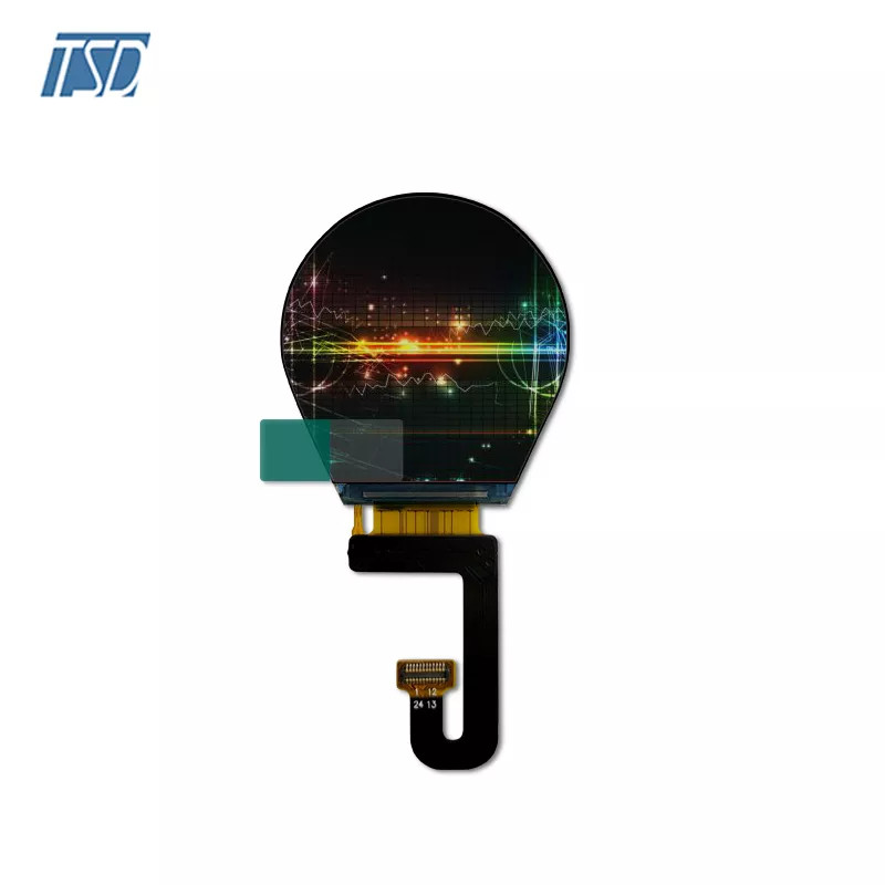
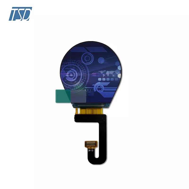
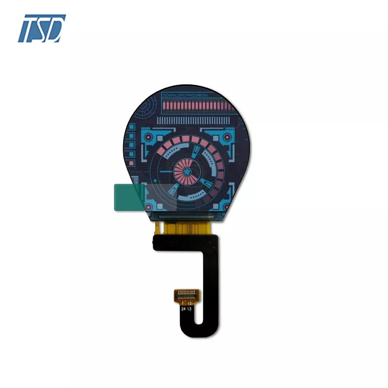
Gallery
![]()
![]()
![]()
Custom Service
Touch panel, LCD, Backlight, FPC
Company Profile
TSD is the professional LCD factory. Providing the TFT display, size range is 0.96-32 inch. And the touch screen including the capacitive & resistive touch panel. Also we have the ability the support provide the mono LCD, customized solution is available.
Our advantages
l 18 Years LCD module experience
l Flexible delivery & cost-effective
l Stable quality
l Professional team
l OEM service
What TSD has?
1)TFT LCD
Size:Our standard TFT LCD display size range from 0.96 inch to 13.3 inch,
including 0.96”, 1.44", 1.77", 2", 2.2'', 2.4", 2.8",3.2", 3.5", 4.3", 5", 5.5”, 7", 8", 10.1", 13.3”.
Brightness: can be designed per customer's requirements
Polarizer: TV, EWV, Ofilm
Connection: All kinds of FPC design supported
2)CTP CAPACITIVE TOUCH PANEL
Structure: G+G, G+F, G+F+F
Cover Lens: Glass (AR, AF, AG coating can be added), PMMA etc.
Driver: FT, GT, Atmel, ILITEK, ST, EETI etc.
Have standard one and also available to make the customization with different size, shape, color, logo etc.
3) Passive LCD
Mode: TN, HTN, STN, FSTN, DFSTN, VA
Structure: LCD Panel, COB, COG
Connection: Zebra,Pin, FPC, Rubber
Backlight: All kinds of design
TSD Touch Panel Solution
1. Customized CTP
Slide, roll, Single-touch, multi-touch, In cell,on cell,G+G,G+F,GGG industry or automotive CTP solution with OCA, OCR optical bonding
2. Customized RTP
Transmittance>94%
Anti static,Anti Dust,water proof
High temperature and humidity
4line and 5lines RTP
3. Cover lens
Customized Color with Silk print, logo printing
Any Irregular Shape
Thickness support
0.55mm, 0.7mm,1.1mm,1.8mm,2.0mm,2.8mm,3mm, 4mm
LIQUID CRYSTAL DISPLAY MODULES
LCD is composed of glass and polarizer. Pay attention to the following items when handling.
(1) Please keep the temperature within specified range for use and storage. Polarization degradation, bubble generation or polarizer peel-off may occur with high temperature and high humidity.
(2) Do not touch, push or rub the exposed polarizers with anything harder than a HB pencil lead (glass, tweezers, etc).
(3) N-hexane is recommended for cleaning the adhesives used to attach front/rear polarizers and reflectors made of organic substances, which will be damaged by chemicals such as acetone, toluene, toluene, ethanol and isopropyl alcohol.
(4) When the display surface becomes dusty, wipe gently with absorbent cotton or other soft material like chamois soaked in petroleum ether. Do not scrub hard to avoid damaging the display surface.
(5) Wipe off saliva or water drops immediately, contact with water over a long period of time may cause deformation or color fading.
(6) Avoid contacting oil and fats.
(7) Condensation on the surface and contact with terminals due to cold will damage, stain or polarizers. After products are tested at low temperature they must be warmed up in a container before coming is contacting with room temperature air.
(8) Do not put or attach anything on the display area to avoid leaving marks on.
(9) Do not touch the display with bare hands. This will stain the display area and degrade insulation between terminals (some cosmetics are determinate to the polarizers).
(10)As glass is fragile, it tends to become or chipped during handling especially on the edges. Please avoid dropping or jarring.
INSTALLING LCD MODULE
Attend to the following items when installing the LCM.
(1) Cover the surface with a transparent protective plate to protect the polarizer and LC cell.
(2) When assembling the LCM into other equipment, the spacer to the bit between the LCM and the fitting plate should have enough height to avoid causing stress to the module surface, refer to the individual specifications for measurements. The measurement tolerance should be ±0.1mm.
ELECTRO-STATIC DISCHARGE CONTROL
Since this module uses a CMOS LSI, the same careful attention should be paid for electrostatic discharge as for an ordinary CMOS IC.
(1) Make certain that you are grounded when handing LCM.
(2) Before removing LCM from its packing case or incorporating it into a set, be sure the module and your body have the same electric potential.
(3) When soldering the terminal of LCM, make certain the AC power source for the soldering iron does not leak.
(4) When using an electric screwdriver to attach LCM, the screwdriver should be of ground potentiality to minimize as much as possible any transmission of electromagnetic waves produced sparks coming from the commutator of the motor.
(5) As far as possible, make the electric potential of your work clothes and that of the workbenches to the ground potential.
(6) To reduce the generation of static electricity , be careful that the air in the work is not too dried. A relative humidity of 50%-60% is recommended.


